Diferencia entre revisiones de «Unimod 2D-B1: Assembling»
De WikiRobotics
(→Links) |
|||
| (No se muestran 6 ediciones intermedias del mismo usuario) | |||
| Línea 16: | Línea 16: | ||
|} | |} | ||
| − | == | + | == Assembing == |
| − | === ''' | + | === '''Step 1''': <font color=blue>Screw the MY1 module to Unimod B1</font> === |
{| | {| | ||
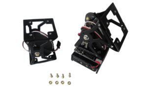
| − | || [[Imagen:Unimod-2D-B1-paso1-1-r2.jpg|thumb|300px|'''1)''' | + | || [[Imagen:Unimod-2D-B1-paso1-1-r2.jpg|thumb|300px|'''1)''' Place the MY1 module and Unimod B1 as shown in this picture''(Click to enlarge)'']] |
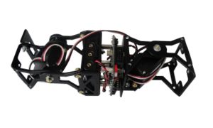
| − | || [[Imagen:Unimod-2D-B1-paso1-2-r2.jpg|thumb|300px|'''2)''' | + | || [[Imagen:Unimod-2D-B1-paso1-2-r2.jpg|thumb|300px|'''2)''' Join the MY1 module with Unimod B1 ''(Click to enlarge)'']] |
|---------- | |---------- | ||
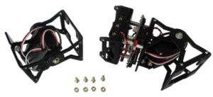
| − | || [[Imagen:Unimod-2D-B1-paso1-3-r1.jpg|thumb|300px|'''3)''' | + | || [[Imagen:Unimod-2D-B1-paso1-3-r1.jpg|thumb|300px|'''3)''' Screw the MY1 module to Unimod B1 Unimod B1''(Click to enlarge)'']] |
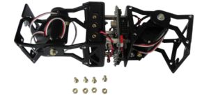
| − | || [[Imagen:Unimod-2D-B1-paso1-4-r1.jpg|thumb|300px|'''4)''' | + | || [[Imagen:Unimod-2D-B1-paso1-4-r1.jpg|thumb|300px|'''4)''' Place the 4 bolts and nuts ''(Click to enlarge)'']] |
|} | |} | ||
| − | === ''' | + | === '''Step 2''': <font color=blue>Connect the module's servo to the Skycube board</font> === |
| − | + | Connect the module's servo to the Skycube board. It can be connected to any of the available 3-pin headers. | |
{| {{tablabonita}} | {| {{tablabonita}} | ||
| − | | [[Imagen:Icono_aviso.png]] <font color=red> | + | | [[Imagen:Icono_aviso.png]] <font color=red>IMPORTANT!</font> Connect the servo in the correct orientation. The black wire is connected to GND |
|} | |} | ||
{| | {| | ||
| − | || [[Imagen:Unimod-2D-B1-paso2-1-r1.jpg|thumb|300px| '''1)''' | + | || [[Imagen:Unimod-2D-B1-paso2-1-r1.jpg|thumb|300px| '''1)''' Connect the servo to the Skycube ''(Click to enlarge)'']] |
| − | || [[Imagen:Unimod-2D-B1-paso2-2-r1.jpg|thumb|300px| '''2)''' Unimod-2D B1 | + | || [[Imagen:Unimod-2D-B1-paso2-2-r1.jpg|thumb|300px| '''2)''' Unimod-2D B1 is ready! ''(Click to enlarge)'']] |
|} | |} | ||
| − | == | + | == Pictures == |
{| {{tablabonita}} | {| {{tablabonita}} | ||
| − | | [http://fotos.iearobotics.com/index.php?album=unimod-2d | + | | [http://fotos.iearobotics.com/index.php?album=unimod-2d Photo album] |
|} | |} | ||
| − | == | + | == Links == |
| + | * [[Training on modular snake robots|Training on modular snake robots (Main page)]] | ||
| + | * [[Unimod]] | ||
* [[Unimod 2D]] | * [[Unimod 2D]] | ||
| − | + | * [[Módulos MY|MY1 modules]] | |
| − | * [[Módulos MY]] | + | * [[Skycube|Skycube board]] |
| − | * [[Skycube| | ||
| − | == | + | == News == |
| − | * ''' | + | * '''23/Feb/2011''': This page is created |
| − | |||
[[Categoría:Robots modulares]] | [[Categoría:Robots modulares]] | ||
Revisión actual del 10:06 23 feb 2011
Contenido
Introduction
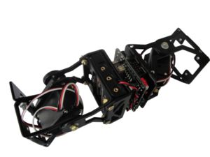
Unimod 2D is the minimal block that oscillates in two perpendicular planes. One module pitches and the other yaws. It is the minimal common element for building pitch-yaw modular snake robots.
To assemble it the following parts are needed:
- One MY1 module (Assembly instructions)
- One Unimod type B1 (Assembly instructions)
- 4 M3 bolts. Length: 8 mm
- 4 M3 nuts
Assembing
Step 1: Screw the MY1 module to Unimod B1
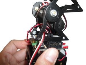
Step 2: Connect the module's servo to the Skycube board
Connect the module's servo to the Skycube board. It can be connected to any of the available 3-pin headers.
| |
Pictures
| Photo album |
Links
News
- 23/Feb/2011: This page is created

