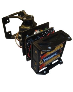
Unimod A1: Assembling
De WikiRobotics
Contenido
- 1 Introduction
- 2 Assembling
- 2.1 Step 0: Remove the paint from the inside of the Part B drills (Optional)
- 2.2 Step 1: Place the male/female spacers in the part D
- 2.3 Step 2: Screw the battery pack to the part D
- 2.4 Step 3: Screw the Skycube board to the part D
- 2.5 Step 4: Screw the MY1 module to the Skycube board
- 2.6 Step 5: Connect the servo and the power supply
- 2.7 Step 6: Install the batteries
- 3 Pictures
- 4 Links
- 5 News
Introduction
Unimod is the minimal module capable of oscillating autonomously. To assembly the following parts are needed:
- A MY1 module fully assembled (Assembly instructions)
- A Skycube board
- A flat battery pack for 4 AAA batteries ready to use (Instructions)
- The part D
- 4 male/female spacers. Size M3, length 12mm
- 4 spacers (female/female). size M3, length 10mm
- 8 M3 bolts. Length: 6mm
- 2 M3 flat head bolts. Length: 8mm.
- 2 M3 nuts
Assembling
Step 0: Remove the paint from the inside of the Part B drills (Optional)
As was done when assembling the MY1 modules, optionally the paint in the part B drills can be removed. This way, the bolts are inserted smoothly in the drills.
Step 1: Place the male/female spacers in the part D
Step 2: Screw the battery pack to the part D
- Place the flat head bolts in the battery pack drills
- Place the battery pack under the part D and place the nuts
| |
Step 3: Screw the Skycube board to the part D
| |
Step 4: Screw the MY1 module to the Skycube board
| |
Step 5: Connect the servo and the power supply
- Connect the servo to the Skycube board to any of the 3-pin header available (corresponding to servos number 2, 4, 6 or 8). The black wire should be pointing to the outside of the module.
- Connect the battery pack to the Skycube:
Step 6: Install the batteries
- Finally, place the 4 AAA batteries in the battery pack. Turn on Unimod to test the power supply connection. The red led should be on.
Pictures
| Photo album |
Links
News
- 20/Feb/2011: This page is created!


