Diferencia entre revisiones de «Minicube-I: Assembling»
De WikiRobotics
(→Montaje) |
(→Paso 2: Conectar el servo a la Skycube) |
||
| Línea 28: | Línea 28: | ||
|} | |} | ||
| − | === ''' | + | === '''Step 2''': <font color=blue>Connect the servo to the Skycube board</font> === |
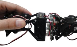
| − | + | Connect the servo to the Skycube boad. It can be connected to any available 3-pin header. | |
{| {{tablabonita}} | {| {{tablabonita}} | ||
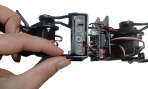
| − | | [[Imagen:Icono_aviso.png]] <font color=red> | + | | [[Imagen:Icono_aviso.png]] <font color=red>IMPORTANT!</font> Connect the servo in the correct orientation!. The black wire should be pointing upward. |
|} | |} | ||
{| | {| | ||
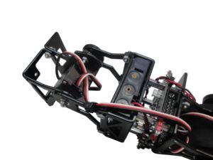
| − | || [[Imagen:Montaje-Minicube-I-paso2-1-r1.jpg|thumb|300px| '''1)''' | + | || [[Imagen:Montaje-Minicube-I-paso2-1-r1.jpg|thumb|300px| '''1)''' Connect the servo to the Skycube board ''(Click to enlarge)'']] |
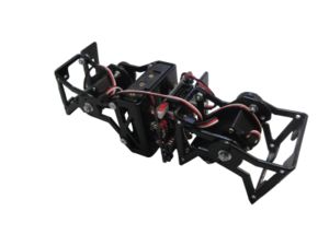
| − | || [[Imagen:Montaje-Minicube-I-paso2-2.jpg|thumb|300px| '''2)''' | + | || [[Imagen:Montaje-Minicube-I-paso2-2.jpg|thumb|300px| '''2)''' View of the connection of the to servos to the Skycube board''(Click to enlarge)'']] |
|--------- | |--------- | ||
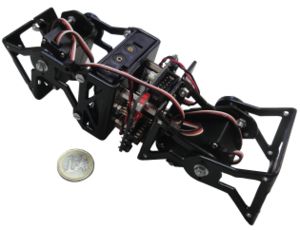
| − | || [[Imagen:Montaje-Minicube-I-paso2-3-r1.jpg |thumb|300px| '''3)''' | + | || [[Imagen:Montaje-Minicube-I-paso2-3-r1.jpg |thumb|300px| '''3)''' The robot is ready ''(Click to enlarge)'']] |
|| | || | ||
|} | |} | ||
Revisión del 01:14 23 feb 2011
Contenido
Introduction
Minicube-I is the minimal modular robot capable of moving forward and backward. For the assembling the following parts are needed:
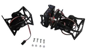
- One MY1 module fully assembled (Assembly instructions)
- One Unimod type A1 (Assembly instructions
- 4 M3 bolts
- 4 M3 nuts
Assembling
Step 1: Screw the module to Unimod A1
Step 2: Connect the servo to the Skycube board
Connect the servo to the Skycube boad. It can be connected to any available 3-pin header.
| |
Paso 3 (Opcional) Fijar los cables con bridas
Este paso es opcional. Para que los cables no molesten se pueden sujetar con bridas. Antes de apretar las bridas, asegurarse de que los módulos se mueven correctamente y que los cables no se tensan demasiado.
Fotos
| Álbum de fotos |
Enlaces
Noticias
- 16/Marzo/2010: Primera versión de esta página
- 10/Marzo/2010: Comenzada esta página
