Diferencia entre revisiones de «Cube3: Assembling»
De WikiRobotics
(→Introduction) |
(→Noticias) |
||
| (No se muestran 6 ediciones intermedias del mismo usuario) | |||
| Línea 13: | Línea 13: | ||
|} | |} | ||
| − | == | + | == Assembling == |
| − | === ''' | + | === '''Step 0''': <font color=blue>Perform the previous assembly</font> === |
| − | + | To assembly [[Robot Modular: Cube3|Cube3]] it is necessary to first build the following parts: | |
| − | # [[Minicube-I: Montaje| | + | # [[Minicube-I: Montaje|Build Minicube-I]] |
| − | # [[Módulos MY1:Montaje| | + | # [[Módulos MY1:Montaje|Build one MY1]] |
{| | {| | ||
| − | || [[Imagen:Minicube-I-fin-r2.jpg|thumb|300px| | + | || [[Imagen:Minicube-I-fin-r2.jpg|thumb|300px|Build Minicube-I (''Click to enlarge'')]] |
| − | || [[Imagen:Modulo-y1-lote1-1.jpg|thumb|250px| | + | || [[Imagen:Modulo-y1-lote1-1.jpg|thumb|250px|Assemble one MY1 (''Click to enlarge'') ]] |
|} | |} | ||
| − | === ''' | + | === '''Step 1''': <font color=blue>Screw the module to Minicube-I</font> === |
{| | {| | ||
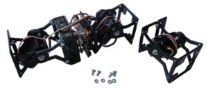
| − | || [[Imagen:Cube3-inicio-r2.jpg|thumb|300px| '''1)''' Minicube-I, | + | || [[Imagen:Cube3-inicio-r2.jpg|thumb|300px| '''1)''' Minicube-I, one MY1 module and 4 bolts and nuts ''(Click to enlarge)'']] |
| − | || [[Imagen:Montaje-Cub3-Paso1-1-r1.jpg|thumb|center|200px| '''2)''' | + | || [[Imagen:Montaje-Cub3-Paso1-1-r1.jpg|thumb|center|200px| '''2)''' Screwing the MY1 module to the Minicube-I robot ''(Click to enlarge)'']] |
|-------------- | |-------------- | ||
| − | || [[Imagen:Montaje-Cube3-Paso1-2-r1.jpg|thumb|300px| '''3)''' Minicube-I | + | || [[Imagen:Montaje-Cube3-Paso1-2-r1.jpg|thumb|300px| '''3)''' Minicube-I is screwed to the MY1 module ''(Click to enlarge)'']] |
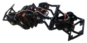
| − | || [[Imagen:Montaje-Cub3-Paso1-3-r1.jpg|thumb|300px| '''4)''' | + | || [[Imagen:Montaje-Cub3-Paso1-3-r1.jpg|thumb|300px| '''4)''' The cube3 robot is ready ''(Click to enlarge)'']] |
|} | |} | ||
| − | === ''' | + | === '''Step 2''': <font color=blue>Connect the servo to the Skycube board</font> === |
| − | + | Connect the module's servo to the Skycube board. It can be connected to any of the free 3-pin headers | |
{| {{tablabonita}} | {| {{tablabonita}} | ||
| − | | [[Imagen:Icono_aviso.png]] <font color=red> | + | | [[Imagen:Icono_aviso.png]] <font color=red>IMPORTANT!</font> Connect the servo in the correct orientation. The black wire should be pointing upwards |
|} | |} | ||
{| | {| | ||
| − | || [[Imagen:Montaje-Cube3-paso2-1.jpg|thumb|300px| '''1)''' | + | || [[Imagen:Montaje-Cube3-paso2-1.jpg|thumb|300px| '''1)''' The skycube board with three connected servos ''(Click to enlarge)'']] |
| − | || [[Imagen:Montaje-Cube3-Paso2-2.jpg|thumb|300px| '''2)''' Cube3 | + | || [[Imagen:Montaje-Cube3-Paso2-2.jpg|thumb|300px| '''2)''' Cube3 is finished''(Click to enlarge)'']] |
|} | |} | ||
| − | === ''' | + | === '''Step 3''' (Optional) <font color=blue>Secure the wires with cable ties</font> === |
| − | + | Optionally, cable ties can be used to secure the wires. This step is similar to [[Minicube-I:_Assembling#Step_3_.28Optional.29_Secure_the_cables_using_cable_ties]] | |
{| | {| | ||
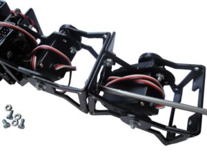
| − | || [[Imagen:Montaje-Cube3-Paso3-1.jpg|thumb|300px| '''1)''' | + | || [[Imagen:Montaje-Cube3-Paso3-1.jpg|thumb|300px| '''1)''' Placing a cable tie for securing the wires ''(Click to enlarge)'']] |
| − | || [[Imagen:Montaje-Cube3-Paso3-2.jpg|thumb|300px| '''2)''' Cube3 | + | || [[Imagen:Montaje-Cube3-Paso3-2.jpg|thumb|300px| '''2)''' The Cube3 robot with cable ties''(Click to enlarge)'']] |
|} | |} | ||
| − | == | + | == Pictures == |
{| {{tablabonita}} | {| {{tablabonita}} | ||
| − | || [http://fotos.iearobotics.com/index.php?album=robot-modular-cube3 | + | || [http://fotos.iearobotics.com/index.php?album=robot-modular-cube3 Photo album] |
|} | |} | ||
| − | == | + | == Links == |
| + | * [[Training on modular snake robots|Training on modular snake robots (Main page)]] | ||
* [[Robot Modular: Cube3]] | * [[Robot Modular: Cube3]] | ||
* [[Robot Modular:Minicube-I|Minicube-I]] | * [[Robot Modular:Minicube-I|Minicube-I]] | ||
* [[Unimod]] | * [[Unimod]] | ||
| − | * [[Módulos MY]] | + | * [[Módulos MY|MY1 modules]] |
| − | * [[Skycube| | + | * [[Skycube|Skycube board]] |
| − | == | + | == News == |
| − | * ''' | + | * '''23/Feb/2011''': This page is created! |
| − | |||
[[Categoría:Robots modulares]] | [[Categoría:Robots modulares]] | ||
Revisión actual del 04:42 23 feb 2011
Contenido
Introduction
Cube3 is a 1D topology pitch-pitch modular robot. It consist of three modules. For assembling it the following parts are needed:
- One MY1 module (Assembly instructions)
- One Minicube-I robot (Minicube-I: Assembling)
- 4 M3 bolts
- 4 M3 nuts
Assembling
Step 0: Perform the previous assembly
To assembly Cube3 it is necessary to first build the following parts:
Step 1: Screw the module to Minicube-I
Step 2: Connect the servo to the Skycube board
Connect the module's servo to the Skycube board. It can be connected to any of the free 3-pin headers
| |
Step 3 (Optional) Secure the wires with cable ties
Optionally, cable ties can be used to secure the wires. This step is similar to Minicube-I:_Assembling#Step_3_.28Optional.29_Secure_the_cables_using_cable_ties
Pictures
| Photo album |
Links
- Training on modular snake robots (Main page)
- Robot Modular: Cube3
- Minicube-I
- Unimod
- MY1 modules
- Skycube board
News
- 23/Feb/2011: This page is created!


