Diferencia entre revisiones de «Unimod B1: Assembling»
De WikiRobotics
(→Steps 0-3: The same than for the Unimod A1) |
(→Noticias) |
||
| (No se muestran 9 ediciones intermedias del mismo usuario) | |||
| Línea 27: | Línea 27: | ||
=== '''Steps 0-3''': <font color=blue>The same than for the Unimod A1</font> === | === '''Steps 0-3''': <font color=blue>The same than for the Unimod A1</font> === | ||
The step from 0 to 3 are exactly the same than for assembling Unimod type A1: | The step from 0 to 3 are exactly the same than for assembling Unimod type A1: | ||
| − | * '''Step 0''': [[Unimod_A1:_Assembling#Step_0:_Remove_the_paint_from_the_inside_of_the_Part_B_drills_.28Optional.29| | + | * '''Step 0''': [[Unimod_A1:_Assembling#Step_0:_Remove_the_paint_from_the_inside_of_the_Part_B_drills_.28Optional.29| Remove the paint from the inside of the Part B drill]] (Optional) |
| − | * ''' | + | * '''Step 1''': [[Unimod_A1:_Assembling#Step_1:_Place_the_male.2Ffemale_spacers_in_the_part_D|Place the male/female spacers in part D]] |
| − | * ''' | + | * '''Step 2''': [[Unimod_A1:_Assembling#Step_2:_Screw_the_battery_pack_to_the_part_D|Screw the_battery pack to the part D]] |
| − | * ''' | + | * '''Step 3''': [[Unimod_A1:_Assembling#Step_3:_Screw_the_Skycube_board_to_the_part_D|Screw the Skycube board to the part D]] |
| + | |||
| + | === '''Step 4''': <font color=blue>Screw the MY1 module to the Skycube board</font> === | ||
| − | |||
{| {{tablabonita}} | {| {{tablabonita}} | ||
| − | | [[Imagen:Icono_aviso.png]] <font color=red> | + | | [[Imagen:Icono_aviso.png]] <font color=red>IMPORTANT!</font> Place the module on top of the Skycube board in the same orientation shown in the picture. |
|} | |} | ||
| + | |||
{| | {| | ||
| − | || [[Imagen:Unimod-B1-paso4-1.jpg|thumb|300px| | + | || [[Imagen:Unimod-B1-paso4-1.jpg|thumb|300px|Skycube board screwed both to part D and to the battery pack, one MY1 module and 4 bolts ''(Click to enlarge)'']] |
| − | || [[Imagen:Unimod-B1-paso4-2.jpg|thumb|300px| | + | || [[Imagen:Unimod-B1-paso4-2.jpg|thumb|300px|MY1 module on top of Skycube. '''Respect the same orientation shown in the picture!''' ''(Click to enlarge)'']] |
|------------ | |------------ | ||
| − | || [[Imagen:Unimod-B1-paso4-3-r1.jpg|thumb|300px| | + | || [[Imagen:Unimod-B1-paso4-3-r1.jpg|thumb|300px|Screw the module to the Skycube board ''(Click to enlarge)'']] |
|} | |} | ||
| − | === ''' | + | === '''Step 5''': <font color=blue>Connect the servo and the power supply</font> === |
| − | * | + | * Connect the servo to the Skycube board to any of the 3-pin headers available (corresponding to servos number 2, 4, 6 or 8). The black wire should be pointing towards the red power switch. |
| + | |||
{| | {| | ||
| − | || [[Imagen:Unimod-B1-paso5-1.jpg|thumb|300px| | + | || [[Imagen:Unimod-B1-paso5-1.jpg|thumb|300px|Unimod with the servo connected ''(Click to enlarge)'']] |
| − | || [[Imagen:Unimod-B1-paso5-2.jpg|thumb|300px| | + | || [[Imagen:Unimod-B1-paso5-2.jpg|thumb|300px|Unimod, with the power supply connected ''(Click to enlarge)'']] |
|} | |} | ||
| − | === '''Paso 6''': <font color=blue> | + | === '''Paso 6''': <font color=blue>Install the batteries</font> === |
| − | * | + | * Finally, place the 4 AAA batteries in the battery pack. Turn on Unimod to test the power supply connection. The red led should be on. |
{| | {| | ||
| − | || [[Imagen:Unimod-B1-paso6-1-r1.jpg|thumb|300px|Unimod | + | || [[Imagen:Unimod-B1-paso6-1-r1.jpg|thumb|300px|Unimod with the 4 AAA batteries installed ''(Click to enlarge)'']] |
| − | || [[Imagen:Unimod-B1-paso6-2-r1.jpg|thumb|300px|Unimod | + | || [[Imagen:Unimod-B1-paso6-2-r1.jpg|thumb|300px|Unimod is on ''(Click to enlarge)'']] |
|} | |} | ||
| − | == | + | == Pictures == |
{| {{tablabonita}} | {| {{tablabonita}} | ||
| − | | [http://fotos.iearobotics.com/index.php?album=montaje-unimod%2Funimod-b1 | + | | [http://fotos.iearobotics.com/index.php?album=montaje-unimod%2Funimod-b1 Photo album] |
|} | |} | ||
| − | == | + | == Links == |
| + | * [[Training on modular snake robots|Training on modular snake robots (Main page)]] | ||
* [[Unimod]] | * [[Unimod]] | ||
| − | * [[Módulos MY]] | + | * [[Módulos MY|MY1 modules]] |
| − | * [[Skycube| | + | * [[Skycube|Skycube board]] |
| − | == | + | == News == |
| − | * ''' | + | * '''23/Feb/2011''': This page is created |
| − | |||
[[Categoría:Robots modulares]] | [[Categoría:Robots modulares]] | ||
Revisión actual del 07:02 23 feb 2011
Contenido
Introduction
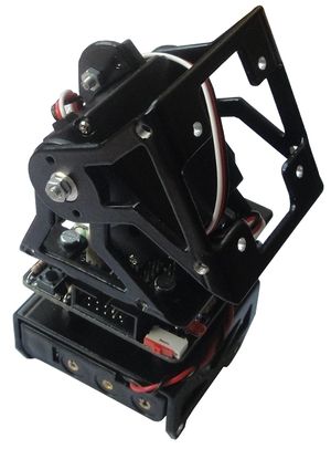
Unimod is the minimal module capable of oscillating autonomously. To assembly it the following parts are needed:
- One MY1 module fully assembled (Assembly instructions)
- One Skycube board
- One flat battery pack for 4 AAA batteries ready to use (Instructions)
- The part D
- 4 male/female spacers. Size M3, length 12mm
- 4 spacers (female/female). size M3, length 10mm
- 8 M3 bolts. Length: 6mm
- 2 M3 falt head bolts. Length: 8mm.
- 2 M3 nuts
Assembling
| |
Steps 0-3: The same than for the Unimod A1
The step from 0 to 3 are exactly the same than for assembling Unimod type A1:
- Step 0: Remove the paint from the inside of the Part B drill (Optional)
- Step 1: Place the male/female spacers in part D
- Step 2: Screw the_battery pack to the part D
- Step 3: Screw the Skycube board to the part D
Step 4: Screw the MY1 module to the Skycube board
| |
Step 5: Connect the servo and the power supply
- Connect the servo to the Skycube board to any of the 3-pin headers available (corresponding to servos number 2, 4, 6 or 8). The black wire should be pointing towards the red power switch.
Paso 6: Install the batteries
- Finally, place the 4 AAA batteries in the battery pack. Turn on Unimod to test the power supply connection. The red led should be on.
Pictures
| Photo album |
Links
News
- 23/Feb/2011: This page is created


