Diferencia entre revisiones de «Unimod A1: Assembling»
De WikiRobotics
(→Paso 2: Atornillar el portapilas a la pieza D) |
(→Step 2: Screw the battery pack to the part D) |
||
| Línea 37: | Línea 37: | ||
=== '''Step 2''': <font color=blue>Screw the battery pack to the part D</font> === | === '''Step 2''': <font color=blue>Screw the battery pack to the part D</font> === | ||
| − | * ''' | + | * '''Place the flat head bolts in the battery pack drills''' |
{| | {| | ||
| − | || [[Imagen:Unimod-A2-paso2-1-r2.jpg|thumb|300px| | + | || [[Imagen:Unimod-A2-paso2-1-r2.jpg|thumb|300px|Battery pack, part D with the spacers, two flat head drills and two nuts ''(Click to enlarge)'']] |
| − | || [[Imagen:Unimod-A2-paso2-2-r2.jpg|thumb|300px| | + | || [[Imagen:Unimod-A2-paso2-2-r2.jpg|thumb|300px|Inserting one bolt in the battery pack drill ''(Click to enlarge)'']] |
|------------ | |------------ | ||
| − | || [[Imagen:Unimod-A2-paso2-3-r2.jpg|thumb|300px| | + | || [[Imagen:Unimod-A2-paso2-3-r2.jpg|thumb|300px|The two bolts placed in the battery pack ''(Click to enlarge)'']] |
| − | || [[Imagen:Unimod-A2-paso2-4-r2.jpg|thumb|300px| | + | || [[Imagen:Unimod-A2-paso2-4-r2.jpg|thumb|300px|Battery pack bottom view, with the bolts inserted ''(Click to enlarge)'']] |
|} | |} | ||
| − | * ''' | + | * '''Place the battery pack under the part D and place the nuts''' |
{| {{tablabonita}} | {| {{tablabonita}} | ||
| − | | [[Imagen:Icono_aviso.png]] <font color=red> | + | | [[Imagen:Icono_aviso.png]] <font color=red>IMPORTANT!</font> Respect the battery pack orientation in reference to part D. The part D is not simetric. |
|} | |} | ||
{| | {| | ||
| − | || [[Imagen:Unimod-A2-paso2-5-r2.jpg|thumb|300px| | + | || [[Imagen:Unimod-A2-paso2-5-r2.jpg|thumb|300px|Place the battery pack in the bottom of the part D. '''Respect the same orientation shown in the picture!!''' ''(Click to enlarge)'']] |
| − | || [[Imagen:Unimod-A2-paso2-6-r2.jpg|thumb|300px| | + | || [[Imagen:Unimod-A2-paso2-6-r2.jpg|thumb|300px|Battery pack screwed to part D ''(Click to enlarge)'']] |
|} | |} | ||
Revisión del 23:51 19 feb 2011
Contenido
- 1 Introduction
- 2 Assembling
- 2.1 Step 0: Remove the paint from the inside of the Part B drills (Optional)
- 2.2 Step 1: Place the male/female spacers in the part D
- 2.3 Step 2: Screw the battery pack to the part D
- 2.4 Paso 3: Atornillar la tarjeta Skycube a la pieza D
- 2.5 Paso 4: Atornillar el módulo MY1 a la Skycube
- 2.6 Paso 5: Conectar el servo y la alimentación
- 2.7 Paso 6: Poner las pilas
- 3 Fotos
- 4 Enlaces
- 5 Noticias
Introduction
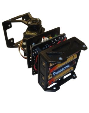
Unimod is the minimal module capable of oscillating autonomously. To assembly the following parts are needed:
- A MY1 module fully assembled (Assembly instructions)
- A Skycube board
- A flat battery pack for 4 AAA batteries ready to use (Instructions)
- The part D
- 4 male/female spacers. Size M3, length 12mm
- 4 spacers (female/female). size M3, length 10mm
- 8 M3 bolts. Length: 6mm
- 8 M3 falt head bolts. Length: 8mm.
- 2 tuercas M3
Assembling
Step 0: Remove the paint from the inside of the Part B drills (Optional)
As was done when assembling the MY1 modules, optionally the paint in the part B drills can be removed. This way, the bolts are inserted smoothly in the drills.
Step 1: Place the male/female spacers in the part D
Step 2: Screw the battery pack to the part D
- Place the flat head bolts in the battery pack drills
- Place the battery pack under the part D and place the nuts
| |
Paso 3: Atornillar la tarjeta Skycube a la pieza D
| |
Paso 4: Atornillar el módulo MY1 a la Skycube
| |
Paso 5: Conectar el servo y la alimentación
- Conectar el servo a la Skycube, en cualquier de los conectores rectos, correspondientes a los servos 2, 4, 6 u 8. El cable negro del servo tiene que apuntar hacia la parte exterior del módulo
- Conectar el portapilas a la Skycube:
Paso 6: Poner las pilas
- Por último, colocar las 4 pilas AAA en el portapilas y encender Unimod para comprobar que la conexión se ha hecho correctamente. El led rojo de power on se deberá encender.
Fotos
| Álbum de fotos |
Enlaces
Noticias
- 28/Febrero/2010: Primera versión terminada
- 24/Febrero/2010: Comenzada esta página


