MY1 modules: assembling
De WikiRobotics
Revisión del 06:09 19 feb 2011 de Obijuan (Discusión | contribuciones)
Contenido
Introduction
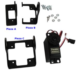
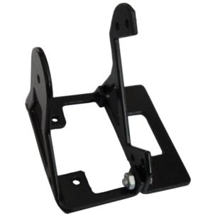
The MY1 modules consist of three aluminium parts: A, B and C and a Futaba 3003 servo. In addition, five M3 8mm-in-length bolts and nuts are needed.
Assembling
Step 0: Remove the paint inside the drills (Optional)
The module parts are made of 2mm width aluminium. They have been painted in black. The inner part of the drills is also painted therefore its diameter is a little bit smaller. In order for the 3mm bolts to go smooth through the drills it is necessary to remove this paint using a rounded file.
Do it for all the holes in all the parts: A, B and C
Step 1: Join the A and B part
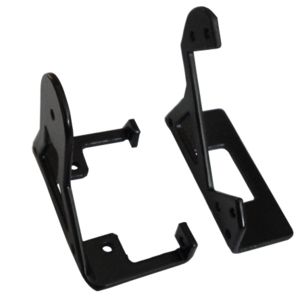
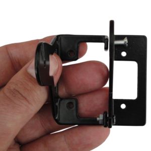
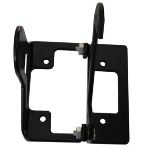
Las piezas A y B se unen mediante dos tornillos y tuercas. Forman el cuerpo del módulo, donde irá atornillado el servo.
- a) Localizar las piezas A y B y orientarlas como se muestra en la figura a.
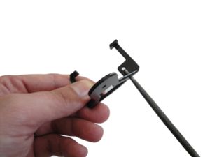
- b) Colocar el tornillo y la tuerca del taladro de la pata inferior de la pieza B.
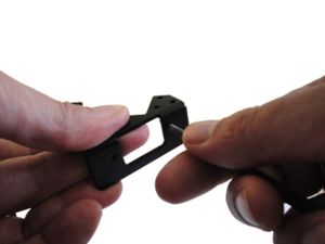
- c) Alinear el taladro de la pata superior con el correspondiente de la pieza A. Es necesario forzar un poco la pieza B.
- d) Colocar el tornillo con su tuerca.

