Diferencia entre revisiones de «Skycube: Mounting the battery pack»
(→Pruebas) |
(→Noticias) |
||
| (No se muestran 6 ediciones intermedias del mismo usuario) | |||
| Línea 79: | Línea 79: | ||
|----------- | |----------- | ||
| [[Imagen:Portapilas-skycube-paso-7-3.jpg|thumb|250px|'''3)''' The molex connector is attached. ¡¡Be careful with the placement of wires!! (''Click to enlarge'')]] | | [[Imagen:Portapilas-skycube-paso-7-3.jpg|thumb|250px|'''3)''' The molex connector is attached. ¡¡Be careful with the placement of wires!! (''Click to enlarge'')]] | ||
| − | | [[Imagen:Portapilas-skycube-paso-7-4.jpg|thumb|250px|'''4)''' The battery pack is finished!]] | + | | [[Imagen:Portapilas-skycube-paso-7-4.jpg|thumb|250px|'''4)''' The battery pack is finished! (''Click to enlarge'')]] |
|} | |} | ||
| Línea 87: | Línea 87: | ||
{| {{tablabonita}} | {| {{tablabonita}} | ||
| − | | [[Imagen:Portapilas-skycube-final-r2.jpg|thumb|250px|Battery pack with 4 AAA batteries]] | + | | [[Imagen:Portapilas-skycube-final-r2.jpg|thumb|250px|Battery pack with 4 AAA batteries (''Click to enlarge'')]] |
|} | |} | ||
| Línea 97: | Línea 97: | ||
{| {{tablabonita}} | {| {{tablabonita}} | ||
| − | | [[Imagen:Portapilas-skycube-test1.jpg|thumb|250px|'''1)''' Connecting the batteries to the Skycube power top connector]] | + | | [[Imagen:Portapilas-skycube-test1.jpg|thumb|250px|'''1)''' Connecting the batteries to the Skycube power top connector (''Click to enlarge'')]] |
| − | | [[Imagen:Portapilas-skycube-test2.jpg|thumb|250px|'''2)''' Switch on the board. The red led will turn on]] | + | | [[Imagen:Portapilas-skycube-test2.jpg|thumb|250px|'''2)''' Switch on the board. The red led will turn on (''Click to enlarge'')]] |
|------------- | |------------- | ||
| − | | [[Imagen:Portapilas-skycube-test3.jpg|thumb|250px|'''3)''' Connecting the batteries to the Skycube power bottom connector]] | + | | [[Imagen:Portapilas-skycube-test3.jpg|thumb|250px|'''3)''' Connecting the batteries to the Skycube power bottom connector (''Click to enlarge'')]] |
| | | | ||
|} | |} | ||
| − | == | + | == Pictures == |
{| {{tablabonita}} | {| {{tablabonita}} | ||
| − | | [http://fotos.iearobotics.com/index.php?album=skycube-portapilas | + | | [http://fotos.iearobotics.com/index.php?album=skycube-portapilas Photo album] |
|} | |} | ||
| − | == | + | == Links == |
| − | * [[Skycube| | + | * [[Training on modular snake robots|Training on modular snake robots (Main page)]] |
| + | * [[Skycube|Skycube board]] | ||
| − | == | + | == News == |
| − | * ''' | + | * '''Feb/19th/2011''': This page is started |
| − | |||
[[Categoría:Hardware]] | [[Categoría:Hardware]] | ||
[[Categoría:Skycube]] | [[Categoría:Skycube]] | ||
Revisión actual del 10:26 19 feb 2011
Contenido
- 1 Introduction
- 2 Mounting
- 2.1 Step 1: Twist the wires
- 2.2 Step 2: Insert the heat shrink tubes
- 2.3 Step 3: Apply solder in the wires ends
- 2.4 Step 4: Apply solder in the molex male pins
- 2.5 Step 5: Solder the pins to the wires
- 2.6 Step 6: Apply heat to the shrink tubes
- 2.7 Step 7: Insert the wirtes into the female molex connector
- 2.8 Step 8: Installing the batteries
- 3 Testings
- 4 Pictures
- 5 Links
- 6 News
Introduction
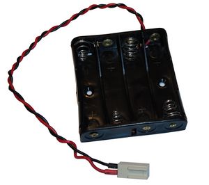
To power the electronics (Skycube board) a flat battery pack of 4 AAA is used. It can be connected to the molex connector on either sides of the board.
The parts needed are the following::
- A flat battery pack, for 4 AAA batteries
- A two-pin female molex connector
- Two pins for the molex connector
- Two pieces of heat shrink tube. Diameter: 2mm. Length: 10mm
Mounting
Step 1: Twist the wires
Twist the battery pack wires. It is optional, but it is recommended to do it. The resulting wire is more compact and resistent. In addition it will easier to wire the robot.
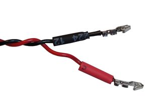
Step 2: Insert the heat shrink tubes
Insert the heat shrink tubes in both wires, as shown in the figure. Do not apply heat still.
Step 3: Apply solder in the wires ends
Use the soldering iron to apply solder in both wire ends. This will make easier to solder the male molex pins
Step 4: Apply solder in the molex male pins
Apply solder in the molex male pins. Just a little bit in the base is enough.
Step 5: Solder the pins to the wires
Solder the pins to the wires. Use a flat nose plier for holding the pin. Bring the wire near the pin and apply heat with the soldering iron. As both the pin and cable have solder their soldering will be done very easily.
Step 6: Apply heat to the shrink tubes
Place the heat shrink tubes in the lower half of each pin. Apply heat with the soldering iron. The shrink tubes will both prevent shortcircuits and make the union more resistent.
Step 7: Insert the wirtes into the female molex connector
Insert the pins into the female molex connector. ¡¡¡PAY ATTENTION TO THE POLARITY!!!. The red wire will be inserted in the hole 1. For inserting it is recommended to use a flat nose plier. If the pin does not enter smoothly use the pliers to smash a little bit the parts that cannot be inserted. When the pin is inserted correctly a slight click will be hear and the wire will not get when pulled.
Step 8: Installing the batteries
Finally install the four AAA batteries. The battery pack is ready for testing!
Testings
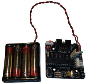
- Connect the batteries to the Skycube power top connector.
- Turn on the board by means of the red switch. The red led will turn on.
- Connect the batteries pack to the power bottom connector. The red led will also turn on.
Pictures
| Photo album |
Links
News
- Feb/19th/2011: This page is started


