Hace un año que nació R2D2…

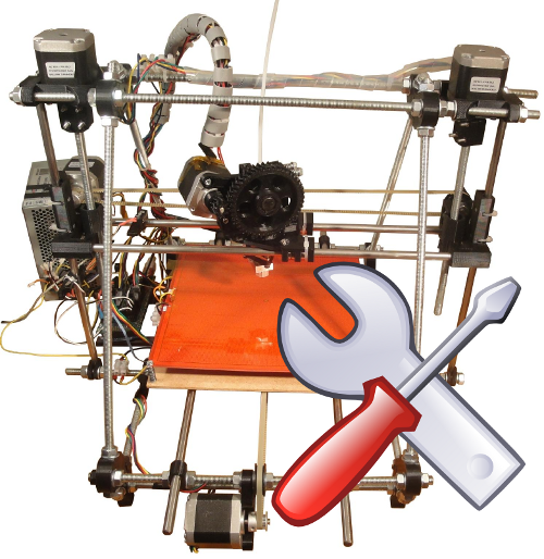
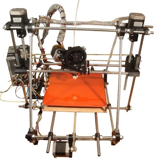
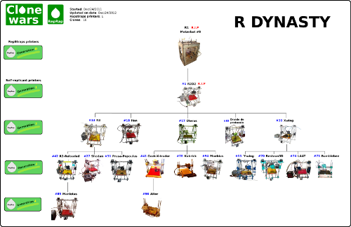
Hace exactamente un año, a las 10h de la mañana, R2D2, el clon #1, imprimía su primera pieza. Un año después somos más de 100 clones en Clone wars. La dinastía R tiene 21 clones y llegan hasta la cuarta generación.

Al día de hoy, en Clone Wars somos más de 500 apuntados a la lista. Hemos documentado las impresoras para que la gente se las pueda fabricar más fácilmente. Estamos probando los últimos modelos: Prusa i3 y Rostock.

Si esto sigue a este ritmo… ¿Cómo estaremos exactamente dentro de 1 año?

Obijuan

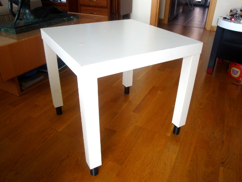
Nuevas patas imprimibles para la mesa de Ikea

Hace unas semanas mi mujer compró una mesa pequeña en IKEA (para ponerla en un rincón). Al llegar a casa y montarla… había un pequeño problema: era demasiado baja. ¿Cómo solucionarlo? Bueno, se podría ir a una ferretería a buscar pies de mesa para alzarla… pero no quedaría exactamente a la altura que quería mi mujer…

¿La solución? Imprimirse unas patas a medida 🙂

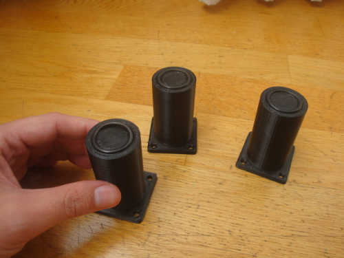
Hice este diseño de pata, en Openscad, derivado de las patas de la tabla de cortar que usé para el robot Robodraw. Para la parte inferior usé las mismas juntas tóricas que uso en los robots (y que tenía en casa), así que no tuve que salir a comprar nada. Esta es una ventaja de hacerte tus propios objetos: los adaptas a lo que tengas.

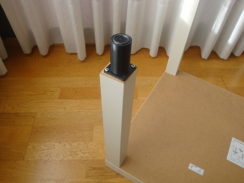
La pata es paramétrica, por lo que la altura se puede cambiar fácilmente. Imprimí una primera pata con la altura estimada y la atornillé a la mesa para comprobar que era la altura correcta. Luego imprimí las otras tres

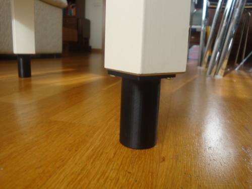
Las patas son muy sólidas y quedaron bien. Mi mujer estaba muy contenta y me dijo “Vale, ahora sí que le veo la utilidad a esto de las impresoras 3D” 😉

Así que ya sabéis, ¿A qué esperáis para construiros una Prusa y hacer felices a vuestras mujeres/novias/madres?

Obijuan

The show must go on…

Soy investigador por vocación. La parte científica de la ingeniería es mi pasión. No disfruto construyendo cosas, sino creando cosas nuevas. Estando en la frontera, generando conocimiento nuevo. Y luego difundiéndolo. Esa es mi motivación.

La situación está muy complicada, y mi carrera docente/investigadora, como la de tantos otros, se ha truncado. Pero la vida sigue y hay que adaptarse.

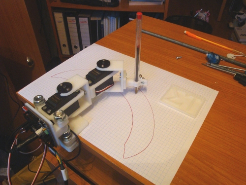
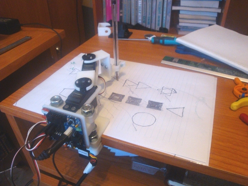
A la espera de que salgan plazas o nuevas oportunidades, la empresa Sigma technologies me ha contratado para un proyecto de 2 meses, sobre robots imprimibles (Printbots). Voy a poder seguir investigando/desarrollando estos robots. Y aunque hay partes confidenciales, el grueso he conseguido mantenerlo libre: materializado como el printbot RoboDraw.

A la empresa le interesa las aplicaciones del robot. A mí su metodología de diseño. Es un robot paramétrico, diseñado con OpenScad, que estoy usando como excusa para investigar sobre nuevos paradigmas de diseño en mecánica. En realidad es un meta-diseño: me estoy centrando en cómo hago para diseñarlo, e intentar sistematizar y modelar la metodología, para tener un modelo semántico y poder aplicarlo al desarrollo de nuevos lenguajes de descripción de mecánica.

En dos meses apenas avanzaré las investigaciones, pero al menos tengo la financiación para seguir 2 meses más 🙂

Obijuan

Enhancing openscad (II): Bevel library

(First part: Enhancing openscad with the attach library)

Introduction

There is one very common operation that has to be done in nearly all the designs: beveling edges. It can be done on the convex side, for avoiding sharp edges, or on the concave side, for reinforce the part (avoiding the 90 degrees connection between parts).

With the bevel library I am developing doing these two operations is a piece of cake. Let’s see some examples

Beveling the exterior edges

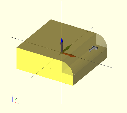
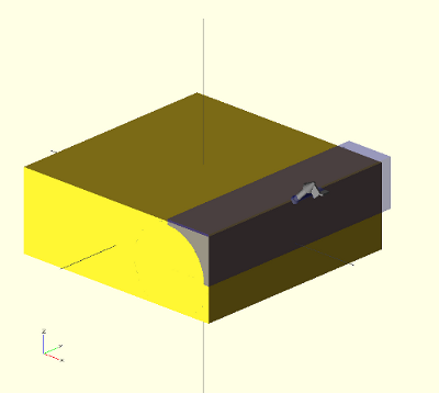
Let’s take a cube as an example. We want to bevel the top-right edge. We will use the concept of connector (the same that is used for the attach operator). First we draw the cube and define two connectors in the same position (the same attachment point). The first one is on the edge we want to bevel. The other is normal and should point to the exterior bisector.

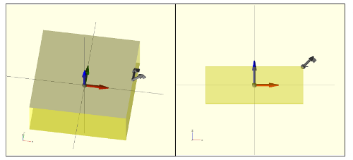
Using the connector() module they can be easily viewed for debugging. It is also useful to make the cube transparent for seeing the connectors better:


size=[40,40,15];

//-- Define the Connectors
//-- position, orientation, 0
ec1 = [ [size[0]/2, 0, size[2]/2], [0,1,0], 0];
en1 = [ ec1[0], [1,0,1], 0];

//-- Debug! Show the connectors
connector(ec1);
connector(en1);

//-- Draw the cube (transparent for debugging)
color("Yellow",0.4)
cube(size,center=true);

Now is when the magic comes:

Invoke the bevel() module, passing the connectors as parameters, as well as the corner radius, the bevel resolution and the length (l). Automatically a beveled concave corner part is placed on the connectors, with the right orientation. In this example the color has been change to transparent blue to see the new part better.


color("Blue",0.4)
bevel(ec1, en1, cr = 8, cres=10, l=size[1]+2);

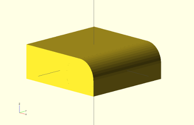
The edge has not been beveled yet… we still have to apply the difference() operator:


difference() {
cube(size,center=true);
bevel(ec1, en1, cr = 8, cres=10, l=size[1]+2);
}

and there it is!

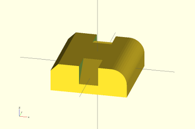
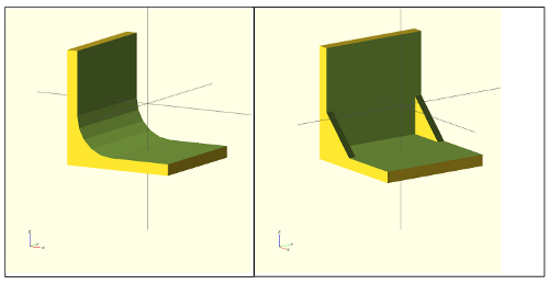
Change the corner resolution, or the radius for modifying the beveling. Also you can easily add more bevel() operations into the difference() so that you bevel more egdes. Here is another part with different kind of beveled edges:

Reinforcing parts: buttress

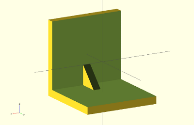
Adding buttress to the union of orthogonal parts is done in a similar way than the edge beveling. First the 2 connectors should be defined, with a vector on the edge direction and another normal to it, pointing to the interior bisector.


//-- part parameters
size=[30,30,30];
th = 3;

//-- Define the connectors
ec1 = [ [0,-size[1]/2+th,-size[2]/2+th], [1,0,0], 0];
en1 = [ ec1[0], [0,1,1], 0];

//-- Show the connectors (Debug)
connector(ec1);
connector(en1);

//-- Part we want to reinforce
color("Yelow",0.5)
difference() {
cube(size,center=true);
translate([0,th,th])
cube([size[0]+2,size[1],size[2]],center=true);
}

Now one buttress is added:


bconcave_corner_attach(ec1,en1,l=th,cr=8,cres=0);

Easy, does not it? 🙂 Again, playing with the parameters, or adding more connectors, different reinforments are created:

Happy Beveling and reinforcing!!!

Obijuan

Enhancing Openscad with the attach library

Looking into the future

OpenScad is one of those tools that opens your mind. It falls into the category of mechanical description languages. Instead of the typical Graphical User Interface (GUI) for designing parts, OpenScad generates the parts from the code typed by the user. This way, the mechanical parts are now pieces of code that can be easily documented, shared among users, uploaded into repositories and so forth.

One of the advantages of this approach is that the code can also be generated by other programs, opening the doors to future design tools that can create physical models from high level specifications. Imagine a software tool able to create robots from the user requests: “I want a mobile robot with tracks, a size lower that xxxx …”. The tool will be in charge of calculating everything and finally offering the user the prototypes that best fit its needs. These tools will also be able to use evolutionary algorithms to build optimized robots or parts.
For programming such tools, we need to combine the power of a standard programming language with the ability to create physical parts. That is one of the goal of the Object Oriented Mechanical Library (OOML): applying the object oriented paradigm for designing parts (in C++). It is a research project for developing new paradigm for designing mechanics.

Back to earth

In the meanwhile, OpenScad is a great tool (and very extended) for developing mechanical parts. There are thousands of designs at thingiverse (tagged with the word “openscad”). Although it is rather easy to design with it, sometimes understanding how others have implemented their parts is a complex task. Even if the code is made by yourself, after some time, it is rather complicated to understand it. There are plenty of translate, rotate and other operators nested in deep blocks of code. Many times is easier to start from scratch than to re-use some code made by others.
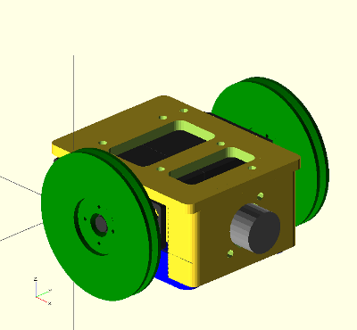
In order to make the code more readable and reusable, I am working on small tools for enhancing openscad designs. One of them is the vector library. Now I cannot live without it 🙂 The new tool I am presenting here is the attach library.

Attaching parts

When designing is rather common to design separated sub-parts as modules that are connected together later. In complex multipart-objects, such as robots, it is also useful to connect all the parts to see how the final design looks.

It is not difficult to do such operations in openscad by means of the translate and rotate operators… but it generates a very difficult to understand code. Here comes the attach operator in our help.

Connectors

In order to write re-usable and understandable code, we have to separated the part data from the code. The first give us the information of the part: size, drills … The second tell us how the object is built from the data (algorithms or approaches). One can choose different algorithms or approaches for building the object from the same data. Separating the data from code makes it possible for others to re-implement the algorithms, therefore improving the parts.

One way of achieving it (for attaching parts) is using connectors, defined as a list of 3 elements: the attachment point, the attachment axis and the roll angle.

Example: defining and using connectors
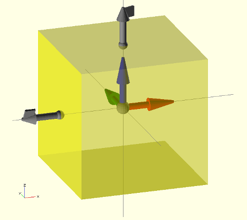

Let’s work on a simple example. Imagine we have a main part in which we want to connect more parts. For simplification, let’s assume the main part is a cube. The first thing to do is to define the connectors. We want to have one on the top and another on the left. Given the cube size by:

size = [20,20,20];

the two connectors can be declared like this:

//-- att. point att. axis roll
c1 = [ [0,0,size[2]/2], [0,0,1], 20 ]; //-- Top
c2 = [ [-size[0]/2,0,0], [-1,0,0], -30 ]; //-- Left

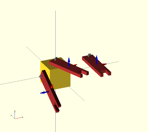
ummm… not very clear up to now… But here comes the connector() module in our help: we can see the cube with its connectors on the screen very easily (See the above image):


connector(c1); //-- Con. 1
connector(c2); //-- Con. 2
frame(l=8); //-- See the frame of reference
//-- Draw the Main part (transparent)
color("Yellow",0.5)
cube(size,center=true);

Now we can see the main part (a transparent cube) along with its frame of reference (module frame()) and the two connectors in gray. The graphical connectors represent their three components with different objects: a sphere on the base for the attachment point, a vector for the attachment axis, and a square mark on the vector head for the rolling angle.
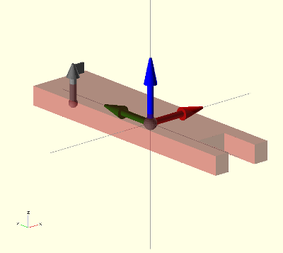
Let’s build the part we want to attach to the main body. We write it like a module, so that the part can be re-used. Again, it is a simplified part, just to show you a simple example. First the part data: size and one connector:


asize = [10,40,3];
//-- Connector
a = [ [0, asize[1]/2-3,-asize[2]/2], [0,0,1], 0];

the module:

module arm(debug=false)
{
  //– Debug mode: show the connector and frame of ref
  if (debug) {
   frame(l=10);
   connector(a);
  }

  color(“Brown”,0.5)
  difference() {
   cube(asize,center=true);

   translate([0, -asize[1]/2,0])
  cube([asize[0]/2, asize[1]/3, asize[2]+1],center=true);
 }
}

Notice that the module has a debug flag, so that when activated the frame of reference and connector are shown:

arm(debug=true);

One, two, three…Attach!
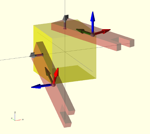

Attaching the parts is now a piece of cake:

attach(c1,a) arm(debug=true);
attach(c2,a) arm(debug=true);

The meaning of the first sentence is pretty clear: Attach the connector a of the arm part to the connector c1 of the main part.

The arm parts are rotated a “roll” angle when attaching. This was the third parameter of the connector. Just changing it, the arms will point to a different place:

//-- att. point att. axis roll
c1 = [ [0,0,size[2]/2], [0,0,1], 80 ];
c2 = [ [-size[0]/2,0,0], [-1,0,0], 90 ];
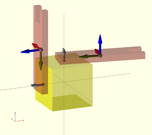
Imagine that a user wants to attach a different part. It is straightforward now to understand the code… just change the arm module by the new part:

attach(c1,b) new_part();

where b is the connector of the new part.

Limitations
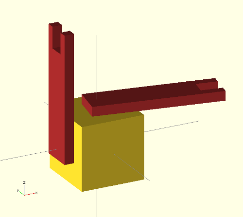
That is how the part looks once you turn off the debug flag.

The attach operator seems to be very powerful and useful.. and it is.. but with limitations. Unfortunately Openscad does not allow defining recursive modules (At least with the 2012-02-22 release).. so when you try to use it on a module that already uses the attach operator…. you will get a warning and your part will not be made…

but …hey! It is opensource software! Yes! it is! So, if the attach operator is useful and the community start using it, it can be implemented natively as an openscad operator… or it can be implemented in higher level mechanical description languages, like ooml (which already include it).

Happy mechanics geeking!

Obijuan
Video-tutoriales de construcción de una impresora 3D de tipo Prusa 2

Ya está terminada la página con los tutoriales de construcción de la Prusa 2. En total han sido 63 vídeo-tutoriales y 189 fotos. Con ello queda totalmente documentada la Prusa 2 para que cualquiera se la pueda construir.

Dentro del proyecto Clone Wars somos ya más de 280 usuarios con un total de 42 impresoras (clones). Además de construir las impresoras, estamos generando documentación, ayudando a los demás y difundiendo el conocimiento y tecnologías libres.

¿Te animas a construir tu Prusa 2? 🙂

Obijuan
Nacimiento de R2-Reloaded

El 28 de Agosto nació R2-Reloaded, mi nueva impresora 3D modelo Prusa 2, con el extrusor Jonaskuehling, hija de R3, nieta de R2D2 y bisnieta de R1.

En realidad R2-Reloaded es la reencarnación de R2D2, que era una Prusa 1 y la quería actualizar a Prusa 2. Imprimí un juego nuevo de pizas con R3, y reutilicé las vitaminas de R2D2 para construir a R2-reloaded. Añadí las vitaminas nuevas para convertirlas en una Prusa 2: Rodamientos lineales, poleas metálicas y correas T2.5 (que R2D2 no tenía).

Si retrocedemos un año en el tiempo, septiembre de 2011, el estado era que yo todavía no tenía ningún clon (sólo tenía la makerbot,R1) y en el proyecto Clone wars no había todavía ningún clon terminado… Ni la Prusa 2 ni la printrbot habían nacido todavía… Ahora mismo tengo 3 impresoras operativas (R3, R3-Reloaded y P1), pero en total he construido 4 (contando a R2D2)… y en el proyecto Clone Wars hay 42 clones!! ¡Todo esto en menos de un año!

Yo no me podía imaginar ni en mis mejores sueños este escenario… como mucho me veía con una impresora (R2D2), no funcionando demasiado bien, y tal vez algunos clones más de Clone wars… así que la pregunta que me viene ahora a la cabeza es… ¿Qué pasará dentro de un año? ¿Cuántos clones habrá? ¿Qué modelos nuevos aparecerán?

Obijuan
Sobreviviendo a las vacaciones (II): La Prusa-Blender

Hola me llamo Obijuan y soy un friki: no puedo parar de aprender y aplicar los nuevos conocimientos para diseñar cosas nuevas, mejorarlas o documentarlas…
La llegada del verano es un placer por la cantidad de tiempo libre para poder pensar sobre esas nuevas ideas y materializarlas… pero… oh wait! Me voy lejos de mi “laboratorio” y lo peor, me quedo sin conexión a internet. ¡Durante 2 semanas! ¡Horror! ¿Qué puedo hacer?

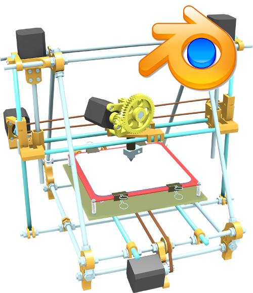
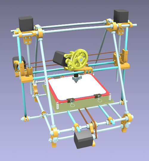
Este año he encontrado la solución. Me he llevado un netbook y un proyecto muy concreto a hacer: dado que no tengo cerca mi impresora… ¿Por qué no construir una impresora Virtual?. Así es como ha nacido la Prusa2-Blender (También publicada en thingiverse)

He aprovechado para aprender algo más de Blender e ir poco a poco ensamblando las piezas de la Prusa2 (que previamente había cargado en el netbook). Las “vitaminas” (piezas no imprimibles de la Prusa) las he diseñado con Openscad y las he importado en Blender. Mi sorpresa ha sido que sin conexión a internet y dedicando unas horillas todos los días (un poco por la mañana y otro poco en la hora de la siesta) he conseguido terminarlo. Y lo más importante, he liberado el frikismo interno 🙂

Aquí os dejo un vídeo que saqué, para que veáis el Blender en acción:

[youtube]http://www.youtube.com/watch?v=7fOu8MF8ZJg[/youtube]

Al llegar a Madrid, lo primero que he echo ha sido publicar la Prusa2-Blender:

* Prusa2-Blender en la wiki
* Prusa2-Blender en Thingiverse
* Prusa2-Blender en github

Obijuan

Sobreviviendo a las vacaciones: Porta-correas imprimible para DVD

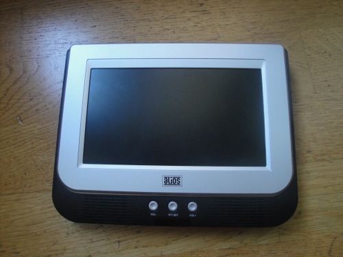
Uno de los horrores del verano es tener que hacer un viaje largo en el coche con 2 niños, de 2 y 4 años. Afortunadamente ahora tenemos esas maravillosas máquinas que son los DVDs portátiles que se ponen en los asientos traseros para que los niños vean películas y estén calmados al menos un rato…

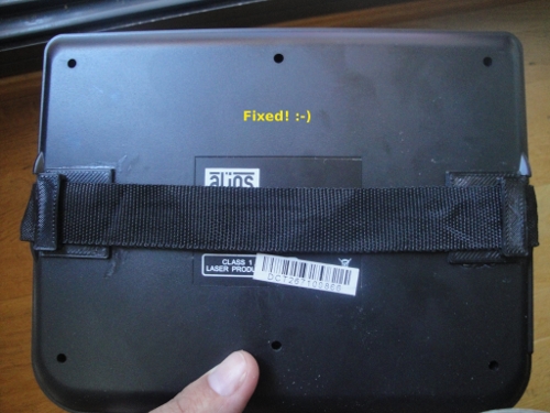
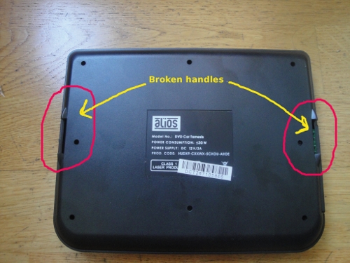
Pero.. ¿Qué pasa si 8 horas antes de salir de viaje descubres que las asas de tu DVD están rotas? “¡¡¡Noooo!!!, tengo por delante un viaje en coche de 6 horas…. y no puedo colocar el DVD en el coche! ¡Horror!”. Pero lo peor era la cara de mi mujer y esa mueca de reproche que indicaba un “¿Ves? ¿Te lo dije? No lo arreglaste el año pasado y ahora nos toca este viajecito“….

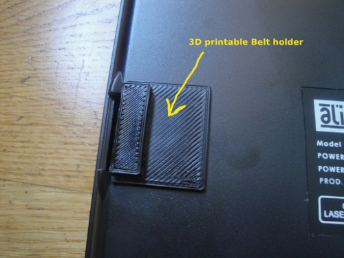
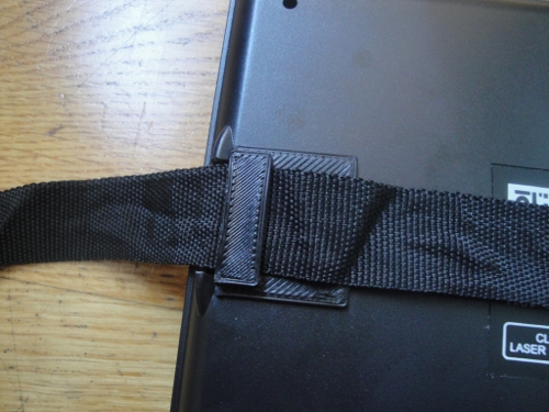
Y entonces recuerdas que tienes unas impresora 3D en casa 🙂 En 20 minutos diseñé este porta-correas imprimible en OpenScad (también está publicado en Thingiverse), lo imprimí en R3, y lo pegué en la parte trasera del DVD. ¡Solucionado!!

Muchos pensaréis que vaya chorrada, que con cualquier otra chapuza lo puedes arreglar. Es cierto, un apaño para el viaje de ida se podía hacer… pero esta reparación ha sido definitiva, y además se puede compartir con la comunidad y reutilizarlo directamente para otros DVDs. Yo lo he tenido que diseñar, pero ahora cualquiera lo puede imprimir directamente (y por supuesto modificarlo y adaptarlo a sus correas).

Obijuan

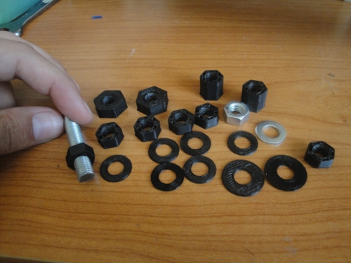
Tuercas y arandelas M8 imprimibles

Ya tenemos tuercas imprimibles M8 (También en thingiverse), ¡¡totalmente funcionales!! Están basadas en la fabulosa librería para OpenScad: ISO Metric thread library hecha por Trevor Moseley.

Además de imprimir tuercas y arandelas de dimensiones estándares, el diseño es paramétrico, por lo que podemos cambiar también la altura y el diámetro exterior. Es decir, que nos podemos hacer tuercas M8 a las medidas de nuestras necesidades. Todo a un golpe de impresión 🙂

En este vídeo podéis ver una demo de las tuercas y arandelas en funcionamiento:

[youtube]http://www.youtube.com/watch?v=xHMjs-O9nq0[/youtube]

¡¡Ya podemos empezar a imprimirlas a granel!! 🙂

Obijuan